Tuesday, November 10, 2009

Google FusionTables and Construction

Recently I came across a new Google feature called Fusion Tables. Like excel Fusion Tables allows a user to visualize database information. When browsing the possible visualization types I found Maps to be the most intriguing.

When I inserted a database I had listing several construction companies and their basic locations in the US I was able to instantly get a Google Map with points indicating the central office locations
.


Not only does this allow you to generate a map of locations, but it also generates a Google Earth File for additional visualization. So what can this tool do for a project?

I have two examples I'll try and explain. First imagine a project going for LEED accreditation. To demonstrate credits for material locations a database of material suppliers and manufacturers can be input in to FusionTables along with the addresses of said suppliers. This can be used to generate a map to illustrate where the materials are coming from.

The second example involves a major construction company with subcontractors all over the country (or a sub with many suppliers). Input all addresses from a database and generate a map so when a new project is up for bid, local contractors and subs can be used.

Sunday, November 8, 2009

The Woolworth Building, Top/Down Construction, & William Starrett

I have passed the Woolworth Building 100+ times in my life. When it was built in 1910, the project was the tallest structure in the world and kept the title for nearly 18 years when it was surpassed by the Bank of Manhattan Trust Building and later dropped to third place by the Empire State Building in 1929. With the 100th anniversary approaching I think that the construction techniques of 1910 were not only impressive for its time, but almost 100 years later are still valid and should be studied by builders.


Persons schooled in architecture and construction are familiar with the basic construction progression of excavation, foundation, substructure, superstructure, and so on up to completion. What struck me when reading The Master Builders (a public-domain book I found on Google Book search) was the innovative method of construction progression used on this project. This project used what is today called Top/Down Construction, but used it 100 years ago to speed the delivery of the excavation, foundation, substructure, and superstructure all at the same time and thus reduce the overall project time.

Excerpts from THE MASTER BUILDERS; by Hugh McAtamney & Co, 1913

BUILDING THE FOUNDATIONS
...the underground work of the Woolworth Building called for the largest single pneumatic caisson contract ever let in New York City or elsewhere. This work consisted of two main items; the sinking of the piers and the deep cellar excavation. Sixty-six reinforced concrete piers from ten to twenty feet in diameter, were sunk approximately one hundred and ten feet deep. They were installed by the pneumatic caisson process, and founded on bed rock. The material penetrated consisted entirely of the most treacherous material known to builders and engineers-quicksand.

... After the piers were completed the erection of the steel work began at once, it being possible to do this because of special cofferdams which had been installed on the tops of the piers. This saved considerable time in the ultimate completion of the building inasmuch as the steel work was not delayed by the general cellar excavation both departments of the construction work being conducted simultaneously.

...this cellar was 55 feet deep. and partly in running quicksand. below water. and that 1.5.000 cubic yards of the quicksand was taken out without interrupting the general work on building. and without jeopardizing the large buildings on all sides the difficulty of the problems will be better understood and the achievement appreciated. This total of the underground work involved an outlay of one million dollars and was accomplished in less than contract time by The Foundation Company of 115 Broadway, New York City.

This project illustrates how Top/Down Construction was executed 100 years ago. First the caissons were drilled. Once they were secured in the bedrock, shoring was installed around the perimeter (although given the contractor, William Starrett, this may have been done at the same time). With the caissons completed structural steel erection could begin. While the steel was moving up, the basement was being excavated.

I cannot describe William Starrett here because I will in no way do him or his career justice. Suffice it to say that William Starrett was the contractor responsible for delivering each of the three tallest structure in Manhattan from 1910 to 1930. These buildings(Woolworth Building, Bank of Manhattan Trust, and Empire State Building) were the World's tallest until the construction of the World Trade Center in 1970, the projects. In addition to these project, Starrett worked for his brother to build the Fuller or Flatiron Building in 1902. So with at least four skyscrapers under his belt it goes without saying that William Starrett deserves some close examination. I have attained a copy of his book 'Skyscrapers and the Men Who Build Them' - 1928 and will eventually post some insights on that text.

To close I want to include a quote from Starretts' Skyscrapers and the Men Who Build Them (1928) which I have taken from editor Carol Lewis' book 'Building the Empire State' (1998):

'Building skyscrapers is the nearest peace-time equivalent of war...The analogy to war is the strife against the elements. ...the service of supply in peace-time warfare, the logistics of building, and these men are soldier of a great creative effort'

Thursday, October 1, 2009

Pourous Concrete Test

This video demonstrates the [AWESOME] ability of pourous concrete. Here it is being deluged with water from a concrete mixer. What is so amazing is how quickly it drains through the concrete.

As I watch this questions flood my mind. How deep does this slab have to be to resist uplift? Is there a special method required for the substructure? Are there special rebar requirements, or other installation requirements?


If anyone out there knows of some helpful links, please drop them in the comments section. So far all I have found is this site for pervious concrete paving.

Parking Garage 093009

Wednesday
10 am

On Wednesday I watched as a steel rebar cage for the new parking garage structure was lifted and set in place. My assumption was that it would simply be lifted and set within a matter of seconds or minutes. The reality was much more involved. Also the crew members and additional equipment was insightful.


Within the steel rebar cage a constellation-like arrangement of bars was located in the center. This I learned was to give the cage stability when going from a horizontal to a vertical position.

A 1-foot portion of the cage had to be to size before it was lifted. A front-end loader was linked to the cut end and used to move scrap to a nearby pile. The loader was repositioned and a chain was used to attach the bottom of the cage to a hook on the loader bucket.

After readjusting the straps which connect to the crane the lift was underway. The loader was used to assist the crane in getting the cage vertical. Once it was vertical and hovering about one foot off the ground, the loader was unchained. Workers then used a torch to remove half of the interior supports. The cage was then lifted to about midway between its lift and final location. Here two workers take what appear to be rigid foam feet to the bottom of the cage. This must provide the required amount of concrete coverage below the cage.

The cage is lifted in to place and lowered to about half way in to the caisson. At this point the cage is held in place while the remaining interior supports are cut and carefully removed so that no rebar fall in to the caisson excavation. With the supports removed the cage is sufficiently flexible and drops right in to place.


I was so impressed with how my assumptions were trumped by the reality of the operation. Last semester we had performed a rough estimate and schedule for caisson work on the new addition to the building department facility. Our estimate focused on the macro estimating and scheduling tasks, but on observing the actual operation I learned the micro-processes. It was a nice reminder that that is what matters. I need to understand the micro-processes in order to truly understand a job. This job is not simply a caisson drill and crane. It is a crew of 8+, a loader, a rebar cage station, drilling spoilage, caisson excavation safety, a welding torch, etc.

Wednesday, September 23, 2009

Parking Garage 092309

Wednesday
12:00 pm
Partly Cloudy

Caisson work is progressing northward. There were an additional two steel workers from the drilling company assembling ReBar. That means that two two-man teams were working simultaneously and within about 15 feet of one another.

The project also presents new insights into building with existing site conditions. The site is a parking lot, which means it is impervious for rainwater. To solve this a drainage pit had to be excavated at the southern end. Also a one-foot berm was created running north-west from the drainage pit. Any water running down over the parking lot is diverted into the pit.

Material storage will be interesting to observe. Once the caisson drilling progresses to the middle of the site, the storage of the caisson sleeves will become an issue that has to be dealt with.

Trailers are all located at the far northern end of the site. Home football game days create traffic congestion so no work is performed on Saturday or Sunday.


In observing a new drainage line that was being installed one can see three pieces of equipment in use. At the far end of the trench an excavator is used to removed the soil. A worker is fitting a drain pipe in a trench barrier. The white machine above the trench is backfilling the trench with stone and soil. In the foreground, one can see a sheepsfoot roller for compaction.


Also got a glimpse of some drainage covers from the Everlasting Vault Company of Randallstown, MD. These vault covers have travelled nearly 300 miles from Maryland to Blacksburg.

More to follow on Wednesday the 30th.
Posted by Picasa


View Larger Map

Friday, September 18, 2009

Parking Garage 091709

Wednesday
9am
Overcast

Construction has been underway at the new parking garage structure on campus. Just over a month ago an enclosing fence, runoff screen, and trailers were installed around the site. The site itself consists of an existing parking area. Trees and curbs were removed with excavators and dozers. Starting last week the caisson entourage showed up on site. Caissons will vary in size from two to four feet diameters. A crane and a caisson drill have begun drilling at the north west corner of the site. This photo was taken from the balcony of building across from the site.


The above photo shows the ReBar construction area. Workers use this space to build the caisson cages on site. This seems to be a space and labor intensive way to work. What is the cost/benefit of constructing on site as apposed to off-site and transporting it. It may have to do with paying for transportation twice (material to shop, shop to site).

The video shows the movement of the steel from the assembly to temporary storage area.

In observing the caisson drilling rig I noticed a safety cage which encircled the caisson excavation. This safety cage was roughly waist height and obviously meant to protect workers on the ground from falling in to the pit. Today I observed the drill rigs space needs. The caisson drilled is parallel or in-line with the tract. To the left was a spoil pile where the drill would shake loose soil (which appeared to be a shale of some sort) and to the right were some additional bits which could be swapped out when needed.
Note to self: consider safety enclosure for caisson, spoil area, removal of spoil, extra drill bits. Also there appeared to be a barrel of oil on the drilling rig which seemed to allow easy access to the drill apparatus.

Thursday, September 17, 2009

Site Visit 090709

Monday September 7th, 2009
Partly Cloudy


Construction of new basketball practice facility is complete. Some minor site work is being completed and the construction enclosure has been reduced to a single trailer, parking, and utility hook-up. They appeared to be taking down a notification board. The trailer looked as if they were packing up to move to the next job. There were some excavators at the rear of the site, but that work seemed connected to a new project down the hill.


Below are two photos taken from a similar perspective. The first shows construction in progress in December. The next shows the finished product.


Construction is where the action is. The 'under construction' photo and phase of the basketball facility has so much more going on. Several months ago a crane was in the middle of leveled area of soil. After the rat slab was poured and the metal decking was installed it was used as a large storage area for various trades. Now it serves a single purpose.
Posted by Picasa

Sunday, August 2, 2009

Construction in Calabria, Italy (Part Two)

Having travelled to this part of Italy several times since I was 6 years old, this visit to the hilltown of Maiera was different. There is a new project in this sleepy hilltown - a 4-star hotel. The town dates back to the 1100s and the hotel occupies a old palazzo (or palace) which is several hundred years old. The Hotel has four levels. The upper most two will contain rooms with private baths, the second level will hold a restaurant and the first level will have the kitchen. An adjacent building will also have rooms and office space.

Above is the entry to the second level. The scaffolding is set up infront of the entry. A hoist is mounted to the upper portion of the scaffold to assist with material transfer. There is a mortar mixing station on the ground level and the upper level adjacent to the scaffolding.


The metal decking is a modular floring which snaps into place providing flooring, a toe-guard, and an access hatch. There are stairs within the structure, but to access the scaffolding an internal ladder and hatch are used. Inside the building existing floors were reconstructed - terracotta forms the deck and concrete with a steel mesh wire provide the compressive strength.

Walls are composed of terracotta or concrete block. Above is an image showing a concrete block wall with electrical chases installed. To understand the process correctly. A mason lays the block and mortar for the wall. The electrician then comes through and chips aways at the block to insert plastic pipe which forms the conduit chase. Then either the mason or electrician come back through and patch the wall. Eventually which wall will have a stucco finish and no wiring will be seen. The wall does not appear to be load bearing.


With a masonry based system with no false or acoustical ceiling, all conduit is run on the floor. The ridges shown in the photo above are conduit runs along the floor of the upper level. These contain electrical lines. Once the plastic tubes are placed they are covered with concrete. Eventually a topping coat of concrete will be placed to level the floor before tile is placed. When I observed this I couldn't help wonder what it is like to work on this type of surface?

I did not learn to exact finish date or other details of the project. I was mainly trying to understand construction techniques and practices. Another entry will explain some bit of the regulations that were posted and practices I observed.

Posted by Picasa


Construction in Calabria, Italy (Part One)

From June 15th to July 24th, my wife and I spent 6 weeks in Calabria Italy. Starting from New York we travelled to London then on to Rome where we took a train south to Scalea, Italia. We spent most of the time with family in Maiera, exploring the hill towns of Maiera, Grisolia, and the surrounding area. During the trip I noticed some construction projects and practices in and around the area we stayed. The next couple of blog entries are set to describe some of the encounters and experiences from this trip.

Above is the new Heathrow Terminal 5 in London, UK. It is essential an emmense roof with several layers of functional space (security, check-in, shops, bars, etc.). The supporting structure is only visible in pieces from other locations. Only when boarding the flight (shown above) can one see the entire structure.


The vernacular architecture of Maiera is agricultural (Much like to barns that dot the American landscape). Buildings are small and located at the very edges of the property. In a society where everyone's livelihood depends on farming, every square meter of space is essential. The introduction of roads (during the 1950s) developed along existing pedestrian pathways.

The structures of the region, as the one shown above, are composed of local stone which are set in locally produced mortar. The striations in the facade show the varied composition of the mortar. The dark spots in the photo are places where scaffolding was tied to the wall during construction. Almost every structure in the area shows these marks of construction. Due to the scarcity of material and the labor involved in providing a finishing coat of stucco, the scaffold voids were left exposed to the elements. The pergola shown on the left-hand side of the building is supported within the scaffold voids. The beautiful women in the center of the photo is my wife. The precise date of construction is unknown, but the approximate age of the structure is said to be over a hundred years.


In Grisolia, a neighboring hilltop town, we came upon this simple structure. In the upper left-hand corner one can see the roof structure without the terracotta tiles. The roof rafters were composed of dry bundled cane, an abundant product which is generally used for agricultural planting (supporting beans, trellises, training tomatoes, etc.). Here the bundles are placed close enough together to support the valley of cupped terracotta tiles. Once two valleys of tile are in place a ridge of terracotta was placed which simultaneously covers the bundled cane rafter and shed water into the terracotta valleys. (Insert Sketch).


The observations on this trip were not limited to historic or vernacular building. Other entries will include a ruined hilltown (Cirella Vecchia), a 4-star construction project in the hilltown of Maiera, and other observations of construction practices.
Posted by Picasa

Friday, June 12, 2009

Backyard Renovation - Phase III


Friday
Mostly Cloudy & Rain

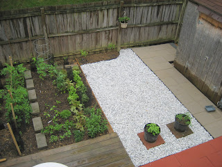
Some photos of the backyard at 98%. There are some pockets here and there that need some gravel infill, but will have to wait. I could not find river stone so I purchased about 25 bags of crushed marble. They were originally all white and covered in powder, but after the rains of the last couple of days several shades of gray have appeared.

Some new Lessons learned have arisen. Having the garden adjacent to the prestine crushed stone with only a thin barrier shows that it will be hard to maintain cleanliness at that edge. In the future I would go with a wider barrier - like a railroad tie or small cement block to widen the distance between dirt and clean stone.

Also you always need more stone then you can estimate. The garden is doing great. We finished up the area near the house with a small curved planting area with some Irish Moss.

To finish up I just have a couple of small pockets to fill in with stone - nothing visible in these photos. Afterward there should be some suttle white lines along the fence and the shed.
Posted by Picasa

Wednesday, June 3, 2009

Backyard Renovation - Phase II

Wednesday - 80 degrees

Today I spent most of the day on Phase II of the backyard renovation. This phase involved 16" gray paving stones that lead from the 12" pavers, along the shed, and to the fence gate.


The installation of paving stone in this phase went much faster. The larger pavers align well with the smaller red pavers. I worked straight through from 8:00 am. During this time I made several trips to the hardware store for stones. One major mistake I made was to try a different hardware chain. I found the "same" 16" paver for $0.30 less so I thought I had it made, but the pavers were slightly smaller and a slightly different shade of gray. I only noticed this once I started to install the second batch of pavers. At first I thought I could incorporate the new pavers, but the gap and color issue was too obvious, so I made yet another trip to get some more pavers and return the smaller pavers. The return ate up 1/2 an hour.

Next, I leveled out the rest of the yard and installed some more of the geotextile fabric. This will provide the base for Phase III - gravel fill. The rest of the yard will be filled with stone and ground covers.

Finally, I incorporated some of the existing bricks and pavers into the new layout. Two large pavers are placed in front of the red pavers and between the gray pavers and deck. The third large reused paver is in the corner near the house (Phase IV - rainwater barrel connected to roof downspout).

I am going to try for Phase III on Friday or Saturday. I want a smooth stone that can be walked upon barefoot. Not sure if I can get that in bags from the chain hardware stores or if I have to shop around and get large pile delivered - I have the next day or so to figure out the logistics. I found the work-a-day, rest-a-day to work well to keep myself motivated.

Some things I learned:
1. The geotextile fabric should be run in the direction of the pavers. Controlling the fabric joints during leveling is difficult.
2. Stick with one material suppliers - they have their own suppliers so there is no way to really guarantee uniform quality.
3. Level a large area of base sand. I was leveling small areas as I went and the smaller pavers have a slight rises and dips.
4. Get a truck. I handled the material sevearl times. I had to load it at the hardware store from the pallete to the cart. From the cart to the trunk. From the trunk to the backyard. From the pile to its final location. Four moves.
5. When stockpiling pavers stagger each one 45 degrees. This small move means easier handling of material from the stockpile to final installation point.
6. Provide temporary shelter. I used a beach umbrella to shade the areas I was working on. This allowed me to keep cool while leveling the base and placing stone. While it did interupt the flow a little, it provided a great relief from the heat.

This was a small exercise. But it has touched on several principles that can be applied to a larder construction scenario. Scheduling, budget control, quality control, delivery and storage of materials, installation methods, material handling, and working conditions.

Phase III to follow.
Posted by Picasa

Backyard renovation- Phase I

Monday I started Phase I of the backyard renovation of our townhouse. The backyard was comprised of a deck, a garden, a loosely laid block storage area and spotty grass. I started with measuring and sketching the backyard to identify major features and begin to estimate materials. The design of the yard was composed of two L-shaped walk ways of different size pavers. The first L-shape path is composed of 12" red pavers and the next L-shape will be made of 16" gray stone.

Next I dug up the grass and started to level the backyard. I had originally thought this would take a single day, but it took several days to dig up the grass and loosen the soil.

Monday morning I bought some material from a chain Hardware Store and began a test of my productivity. I started by laying a geotextile fabric to keep weeds from growing up among the paver stones. Next I placed a layer of sand over the fabric. I leveled the sand by eye using a strip of pressure treated lumber. I was supposed to purchase two pipes and run them parallel in order to lay a uniform level of sand, but decided against it at the last moment. With the sand in place I laid the first six 12" pavers.

After several more trips to the hardware store and some work in the evening with my wife assisting we were able to wrap up phase in a single day. In addition to the pavers I purchased some plastic border strips and stakes to keep a clean separation between the pavers and the adjacent areas.
Phase II involves the installation of the larger - 16" - pavers along the shed and backyard gate. Phase III involves placing stone and installing ground cover to complete the yard.
Posted by Picasa

Wednesday, May 6, 2009

Email Blog Post

Trial post via email. Going to see if attached image will show up in blog.


This was my first attempt at mobile blogging. I just composed the two sentence fragments above, attached a photo and sent it to my blog. Then it appeared in the format above. It seems good for short and quick entries. If more photos were attached they would all be grouped on the top of the post. But, that is where editing can come in. If nothing else I have found a way to cut the post time down by a bit. The photo is of me (small blue object on the right) next to a massive mining dump truck out in Arizona.

Thursday, April 30, 2009

Site Planning & Visualization

For a final project in school we are asked to develop the production plan for the excavation, substructure, superstructure, and masonry and stonework for a proposed addition to our school. Over the course of the semester we had developed these plans individually and for the final project we were asked to combine them. In doing so I decided to use Google SketchUp to visualize the site utilization.


The first image is a view of at the end of the excavation phase. At this point the perimeter fence has been established and the loader and haul trucks are shown in position.

The second image is a view of the caisson installation. Starting at the west the caisson installation will proceed eastward. Then the area to the south will be completed and finally the corner that connects the two. Then grade beams will be formed and poured (this portion was not included in the scope of work, but was included in the model).

The Third image shows the crane location. At this point trailers and restroom facilities have been established on site. The tower crane was selected for its ability to access all parts of the site from one location. Space on the site is limited, so the tower crane helps to alleviate safety hazards and crane relocation issues.

The fourth image is a visualization of the scaffolding from the perpective of a worker on the south side of the building.

This was one of the best benefits of using the SketchUp model It not only allowed a 360-degree 3D view of the site, it also allowed me to see worker perspectives. In a couple of seconds I was able to see what it would be like for a crane operator about to pic a column, stoneworker on scaffolding, and a construction manager or field engineer stepping out of the trailer to see work in progress on the south side of the building (Fifth image).

SketchUp is not a parametric program, it cannot take schedules in to account. But as a free program, it could be used for visualization, and if the proper process was created, I think it could be used for low-level construction animation. The level of detail in the rendering is high, the Google Warehouse has a lot of construction equipment that cuts down on modeling time, and there is the potential to bring models from SketchUp into NavisWorks however, as a zero- or low-cost option, it could prove very helpful in communication with trades.
The Google SketchUp site has a couple of Construction Case Studies showing how professional construction companies use sketchUp for site visualization and safety.

Below is a small video of another project for school in which we were able to bring the SketchUp Model into NavisWorks and automatically synch up the MS Project schedule to it.

Saturday, April 25, 2009

Thermography

10:00 pm
78 degrees
Partly cloudy

I've borrowed a thermal imaging camera from the department. The assignment I have is to learn how to use, what problems arise, and how to better use it in the future. I went out this evening and took some images of the townhouse I live in, then I threw them all into Picasa, then into PhotoSynth to try and stitch them all together and see if you could get a low-cost 3D thermal image.

This is what I got. 8% synth on 80 plus images. I think I have to take two or three times as many in order to get them to synth properly.

What I learned or what I got to see visually was:
1. Brick retained much more heat than the aluminum siding above
2. Bushes, trees, and foliage are cooler, and obstruct readings
3. The outside edge of a facade can be cooler than the interior surface (so there is not an even distribution of heat across a surface).
4. Windows require several images to capture what is really happening
5. Dryer and vent projections require several images in order to capture what is really happening

For instance. Here (above image) is a shot of a dryer vent (shown in the center) from about 20 feet away.
Here (above image) is that same dryer vent from below. You can see that there is a 3.9 degree difference in the readings. Also there seems to be considerable leakage in this area (shown in yellow in both) however, this could be an effect of the outdoor light which was on (first image, lower righthand corner).

Another interesting find was on the indoor imaging. When I shot the west wall I saw that the location of the studs and where the ceiling meets the wall was around 80 degrees, the surface of the wall between the studs was around 78, and the actual joint where ceiling meets wall was above 82.5 degrees. So in a small area there is a 4 degree difference. Albeit not very much, but I am measuring in the spring when the weather is much warmer. So with the rest of the time I have this camera I am going to try a couple of more times to get enough thermal scans to get an image into photosynth.

Wednesday, April 8, 2009

Frontier Culture Museum

Saturday, April 4th
Windy & Clear

ROAD TRIP. No better way to clear the mind than with a roadtrip. Saturday was spent driving up to the Frontier Culture Museum along I-81, in Staunton, VA. The museum is collection of frontier housing types which demonstrate living and working conditions from the 17th to 19th century. There is an English style cottage from the 1600s, some Irish dwellings from the 1700s, a german farmhouse and barns also from the 1700s. On the other side of the property one can find the American frontier houses from the late 1600s to the middle of the 1800s.


View Larger Map

The best part of the trip was seeing the construction of these buildings. The English, and German, and American homes were heavy timber structures. The Irish cottages were stone with some timber framing for the roof.


English cottage (c.1630)

American Farm House (c.1840)


Log Cabin (c.2009)
This is a side view of the log cabin. Interestingly enough the log cabin was brought over by Swedish settlers to Delaware. The employees of the FCM work to show the authenticity of the period. On the way out we watched as one guy split a log for fence rails. While he was quatering the log he asked me if I would like to give it a try.

After finding a crack in the wood he drove some iron wedges in with a small hammer. Then he used a mallet made from a tree stump and branch to start splitting. I got to finish off the last half of it. The picture does not capture the weight of that mallet or the sound. The log made this incredible ripping noise as it was being separated.

When it was all said and done we had had a great day and learned a lot about early frontier archicture and construction.

As a side project: I want to start a side project of trying to find a way to introduce a colonial period kitchen into a modern day kitchen. The kitchens in these buildings were about 10 feet wide and the floor of the room was the hearth. What would it be like to be in a modern day kitchen and able to cook on a stove top as well as bake bread in a brick oven? Something to think about at least.
Posted by Picasa